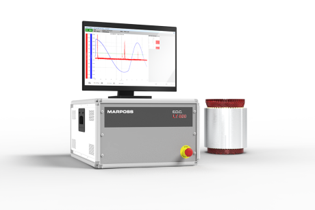
Back EMF Test
When a winding is subjected to a time-varying magnetic field, an induced voltage is produced; the resulting current in turn produces a magnetic field that opposes the field variation that caused it.
In a permanent magnet motor, the current applied to the stator windings creates a magnetic field that interacts with the rotor magnets to produce a drive torque that causes the rotor to rotate. However, because the rotor is fitted with permanent magnets, its rotation creates a variable magnetic field that passes through the stator windings, inducing a voltage in them that is opposite in sign to the supply voltage. This phenomenon is known as back EMF or BEFM and its amplitude is proportional to the speed of the motor.
Back EMF testing on the production line is a critical step in the quality control of electric motors, particularly permanent magnet synchronous motors (PMSMs). As the BEMF is directly proportional to the magnetic field strength generated by the rotor magnets, any anomaly such as a damaged, partially demagnetised or missing magnet will result in a reduction in the BEMF from the expected value. This indicates an anomaly that will affect the performance of the motor.
Depending on the stage of the production process at which you wish to perform the BEMF test, Marposs is able to offer different solutions, adapted to the specific control and verification needs of the component.
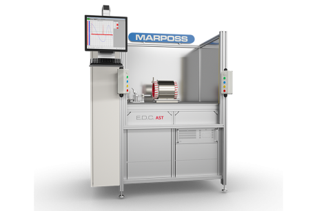
TEST PERFORMED AT THE END OF THE ROTOR ASSEMBLY LINE
At this stage of the process, the rotor has not yet been coupled to the stator. Therefore, in order to perform the test, the test bench must integrate a sample stator as part of the test equipment, at whose terminals induced voltage signals are acquired for back EMF analysis.
A key aspect is the mechanical design of the test bench, which must ensure precise alignment between the rotor and stator during loading, unloading and testing. The robustness and accuracy of this alignment system is essential to ensure reliable and reproducible results, especially for large motors such as those used in electric vehicle traction.
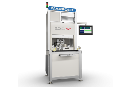
TEST PERFORMED ON COMPLETE MOTOR
The Back EMF test can also be performed on the fully assembled motor in its final configuration, with the rotor and stator already mounted and installed.
This configuration allows two separate test methods to be performed on the motor:
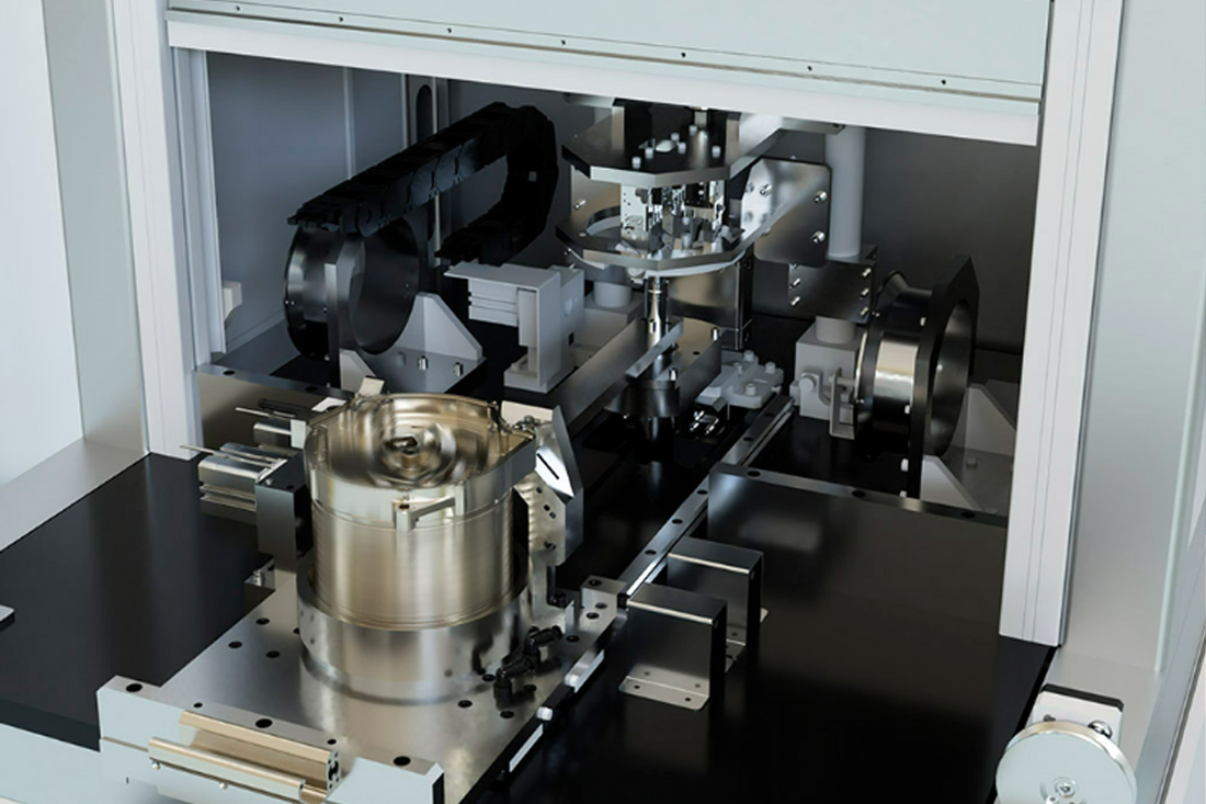
- Back EMF Standard: the motor under test is not powered and is set in rotation by a mechanical coupling with a suitable active brake.
- Back EMF Dynamic: the motor under test is powered and allowed to idle (without applying an external load).
A significant advantage of BEMF testing on a complete motor is that it provides a final assessment of the motor's performance, ensuring that all components, both electrical and mechanical, are perfectly integrated and functional.
DETAILED ANALYSIS OF MAGNETISATION DEFECTS
It should be emphasised that the BEMF test provides very useful functional indications of possible magnetisation defects but may not be able to carry out a detailed analysis of local defects and their causes, which is necessary if the process itself is to be influenced retrospectively.
For this purpose, it may be advisable to use a magnetic field mapping instrument at the end of the rotor production line, using a Hall sensor integrated into a dimensional gauge such as OQL (OptoQuick).
After verifying the correctness of the magnetic field profile on the rotor at the end of the line by direct measurement, it is possible to proceed with the back EMF functional test on the motor, minimising the risk of having to disassemble defective rotors.
The back EMF test on a complete engine can be carried out in one of two main ways:
- Back EMF standard
This is the standard test method traditionally used, in which the motor to be tested remains de-energised and is rotated via a mechanical coupling with an active brake.
Once the motor under test has been brought up to the desired speed, the three phase-to-phase voltages are sampled while the motor is maintained at a constant speed. The following analyses are performed on each of the three signals acquired:
- RMS value (Root Mean Square)
- Maximum peak-to-peak amplitude
- Spectral analysis using FFT (Fast Fourier Transform)
- Total Harmonic Distortion (THD)
- Ripple analysis on the three signals simultaneously
An active brake test bench combined with the AMT320/W system can be used in production to perform other tests in automatic sequence in addition to the BEMF, including Friction Test, Cogging/Torque Ripple Test, Torque Test, etc.
Alternatively, in R&D, the test bench can be used in combination with the ATC320/W system to perform characterisation tests on the engine, ensuring in-depth analysis of its performance.
2. Back EMF Dinamica
In cases where the active brake is not required for other tests, Marposs has developed a special method of acquiring BEMF signals by directly powering the motor under test.
The motor is brought up to the target speed via the inverter and, once this is reached, the system waits for a configurable time interval before automatically disconnecting the inverter. During the subsequent motor deceleration phase, the three phase-to-phase induced voltages are sampled.
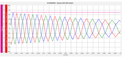
The main advantage of this type of test is the elimination of the active brake, which simplifies the test bench and reduces costs.
Marposs can provide test solutions for both methods, whether for in-line applications with a high degree of automation, or for laboratory or small production benches with a low degree of automation or completely manual.